Crafting quality products to access earth’s valuable resources in a way that sustains us all
30 years of experience in the precision machining of complex metal parts
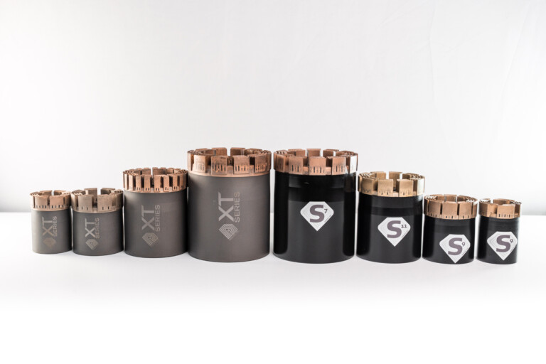
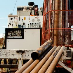
Mineral Exploration Core Bits
Dimatec offers a wide assortment of core bits for drilling all types of geological formations ranging from medium/sedimentary to hard/igneous. The products in this group:
Typically have a cutting structure comprised of a metal-bond matrix that has been impregnated with synthetic diamond crystals
Are compatible with most types of wireline or conventional core barrel systems
Are available for use in both surface and underground drilling applications.
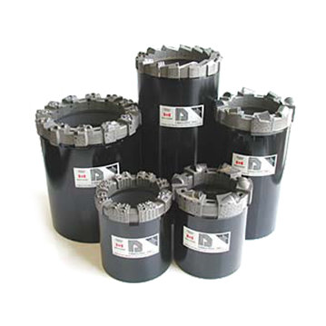
Geotechnical core bits are commonly applied in both the mineral exploration and civil engineering sectors. They are designed for use in drilling the softer, abrasive, and unconsolidated sedimentary formations that are not effectively drilled by diamond impregnated core bits. These formations may range from very soft clay, gypsum or talc up to and including harder types of sandstone.
Unlike diamond impregnated bits, these products feature a single layer of cutting media that are either embedded or mounted in a tough, wear-resistant matrix-body.
Four different types of cutting media are offered in this product range. The primary difference between these types are the:
Cutting media material (natural diamond, synthetic diamond or tungsten-carbide)
Extent of cutter exposure
Cutting media density (number of cutting edges per unit bit face area)
The products in this group are used to: Ream drill holes to industry standard gauge sizes, Stabilize rotating drill string components to control the angular deviation of the drill hole. Reaming tools and stabilizing tools are distinguished by the type of hard material that has been embedded in the tool’s matrix-body ring. Reaming tools are […]
The term “Casing Shoes” represents a group of products that also include rod shoes and casing bits. These products are used when a new drill hole is being established in order to insert a casing tube through the overburden layer. The inserted casing tube subsequently serves as a clear conduit between the surface and the […]
Non-coring bits are used for full-hole drilling operations in which no core sample is collected. Like Dimatec’s core bits, these products are offered with three different types of cutting media. The cutting media selection is dependent on the type of formation that is being drilled. Non-coring bit applications include (but are not limited to): Full-hole […]
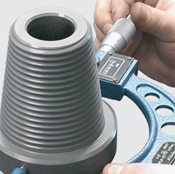
Dimatec offers precision machining services to manufacture production quantities of customer (OEM) designs for machined components. These services are offered primarily to the oil and gas industries.
Dimatec also offers a range of special processes in support of our OEM machined products that include:
Surface wear protection solutions through the integration of powdered-metal matrix bodies into part structures.
Surface treatments such as zinc-phosphate coating and shot peening.
Non-destructive testing (NDT) in the form of liquid dye penetrant inspection (LPI) – both the visible as well the post emulsified fluorescent techniques are available.
We at Dimatec know that while earth’s valuable underground resources continue to provide quality of life to people around the world, not everyone gets to share equally in them. Our “Every Bit Helps” initiative donates proceeds from every Dimatec drill bit sold to organizations working to improve the quality of life for many.
Thank you for partnering with us. Every bit helps.
“We know only too well that what we are doing is nothing more than a drop in the ocean. But if the drop were not there, the ocean would be missing something.”
― Mother Teresa
Testimonials
“325 meters with our bits very good in medium hard rock. Thank you!”
– Ontario, Canada
“The successful trial results of the bit prove this bit to be a serious alternative to our current bit of choice at our mine.”
– Australia
“I have a result from a new client in northern Ontario. Their last bits went 60 or 80 meters and with Dimatec bits 212 meter! Good production thank you.”
– North America
“We received the bits yesterday! We are quite pleased with all aspects of this order including the 4-day lead time. Thank you for the expedited service!”
“The meters drilled were above ‘the norm’ and we were well within and even under budget lets say…”
– Canada
“We had a good wear on the crown, the meters achieved are also worth commenting on being consistently all right around the 300’ mark. We’re happy and the reaming shells are also performing well.”
– North America
About Us
Dimatec is a Canadian manufacturer of high quality metal-bond diamond tools and related down-the-hole drilling equipment. Our products are used globally by the mineral exploration, geotechnical survey and the oil and gas industries.
Since the company’s formation in 1988, Dimatec has strived to develop new and innovative products to meet the changing needs of the drilling industry.